
After nearly five years of living, working and cruising on “Old Nick”, managing the Electric Narrowboats FB group and organising Electrika for two years, we have had lots of opportunities to observe, discuss and ponder on what makes the perfect serial electric hybrid narrowboat.
This article will try and distill what we have learnt, in the hope that it will help other potential owners to specify a suitable serial hybrid for their needs and help boat builders to design a balanced and desirable electric narrowboat.
A serial electric hybrid (aka series hybrid) is currently the most efficient, “Greenest” Narrowboat design available. Propulsion is performed by the electric engine and an efficient, low RPM, inboard diesel generator is used to charge the battery bank (if needed) providing a “safety net” that makes continuous cruising possible on the UK canal system.
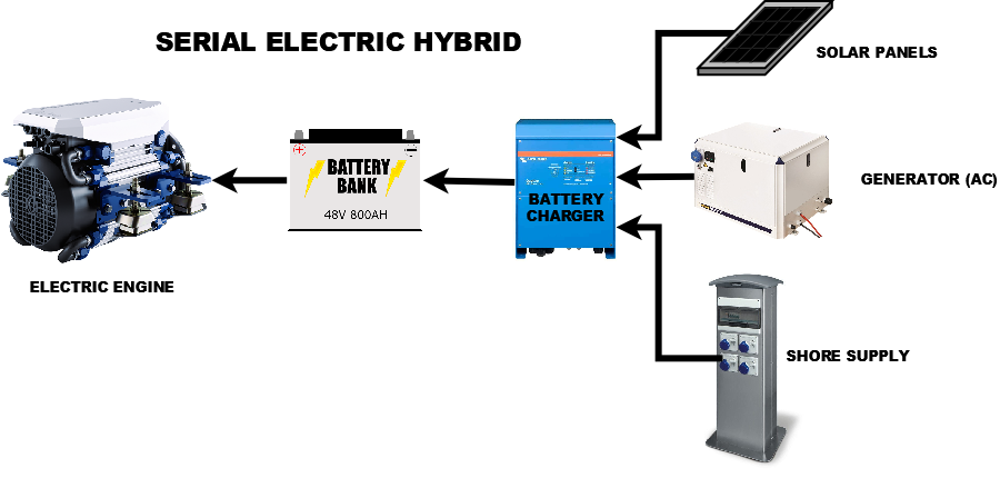
In addition to the diesel generator, power can also be provided by solar panels and, when in a marina, by shore power supply. We estimate that, over the course of our cruising season, our diesel usage is 30% of a comparable diesel powered narrowboat.
All About Balance
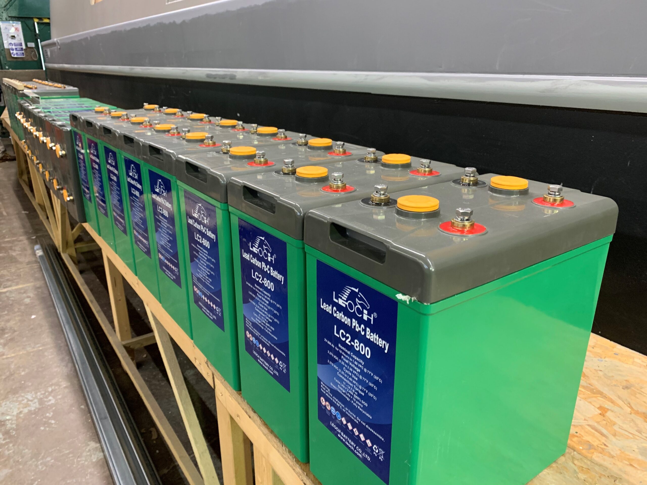
When it comes to the key components in the serial hybrid system, our advice would be to go as large as possible (budget permitting), you will not regret it. We originally specified a Victron Quattro 48v/5000VA, Leoch 48v 600A/Hrs Lead Carbon batteries and 8 x 160W (1280W) Solar Panels for “Old Nick”. Then at the eleventh hour, we decided to upgrade to a 48v/8000VA Quattro, 800A/Hrs of batteries and 12 solar panels (1920W) and although it stretched our budget to breaking point, it was definitely the right decision.
With some of the components, you will have physical limitations that restrict how large you can go i.e. space in the engine room or roof space for solar panels. Once you have identified your physical and budgetary limits, it is important that you then make sure the balance is right.
There is no point having a massive battery bank if it is going to take forever to charge them up, and there is no point having a massive generator, if your battery charger cannot handle all of the power it receives.
The Engine
Starting with the engine, in reality, on a typical 55-60ft narrowboat, your electric engine is going to spend most of its time consuming between 0.5kW (1.5 MPH) and 5kW (3.5 MPH) of power, depending upon the speed you like to cruise at. On “Old Nick” we like 2MPH at 1kW, so that when the sun is out, we experience what we call “State of Nirvana” – free propulsion.
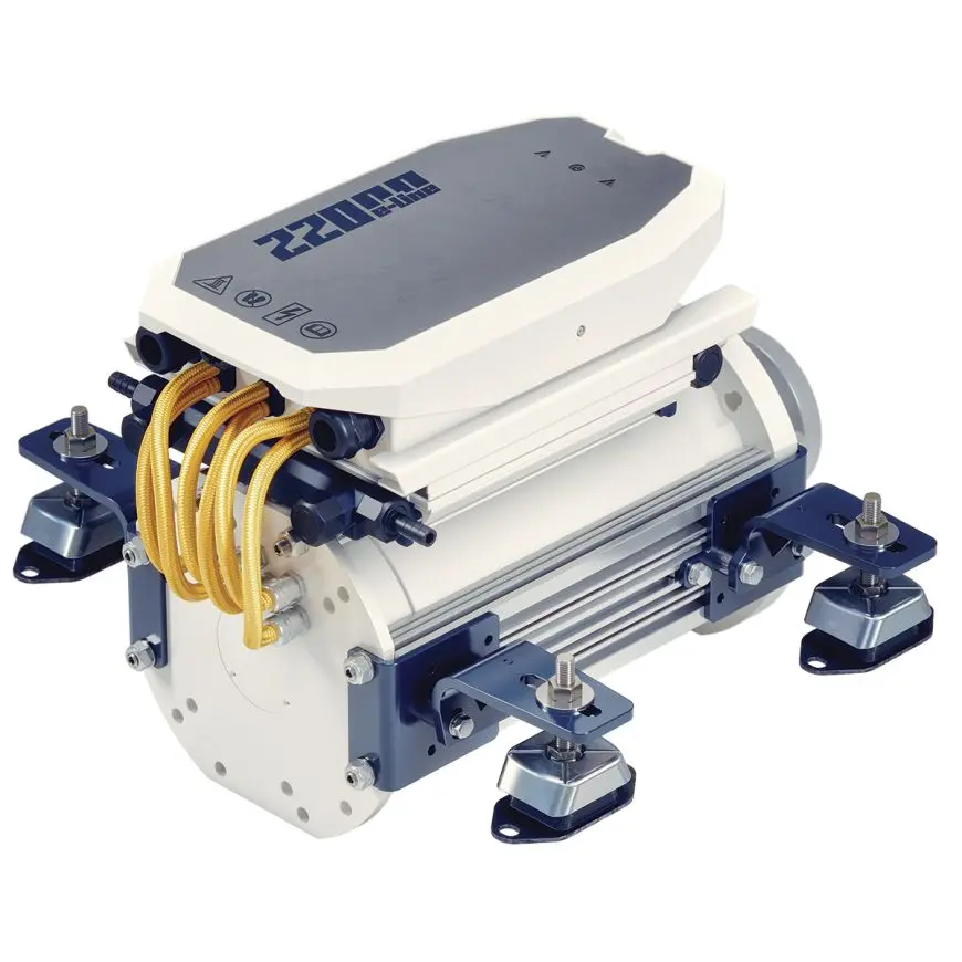
Out 10kW Vetus E-Line engine has done us proud over the last 5 years, but if we were doing it all again, we would probably go for their new larger 22kW engine, which was not available at the time, but which Vetus recently launched (image below). We would also look at some of the latest low RPM, high torque, permanent magnet AC motors (PMAC), from such companies as; Lightning Craft, Torkmar, etc. which can turn larger propellers and profess to offer higher efficiencies and lower operating temperatures than other types of electric motors..
The Prop
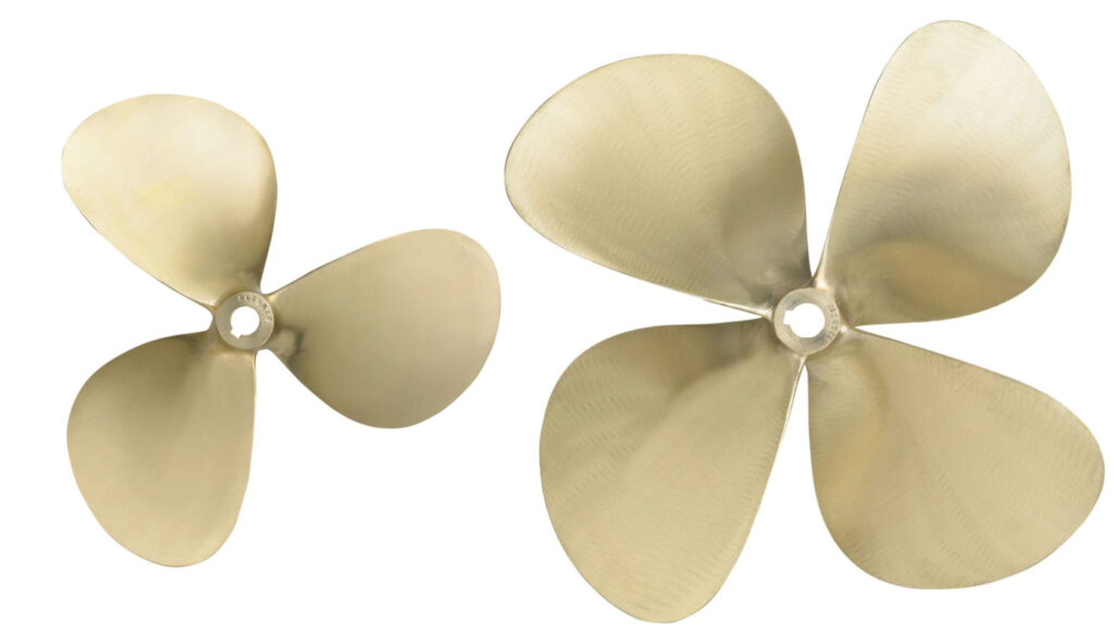
It is very important that you correctly match the engine to a suitably sized prop. We are now running a 16″x12″ 4 blade, after replacing the original 13″x9″ 3 blade that Vetus supplied, and are very happy with this. Our larger prop is quieter (biggest reason for change) and accelerates and stops much quicker. We can no longer get the full 10KW power out of the engine, as larger props cause electric engines to hit their “torque limit” at lower power output, but as we have never needed the full 10KW of power in 3-4 years of use, we consider this a small price to pay for the other improvements.
In general a larger KW engine, is able to turn an even larger prop – see the results of Ortomarine’s recent Prop Trial for more information – but the design of your hull, in particular the skeg to prop shaft and prop shaft to uxter plate distances will decide the largest size of prop you can realistically fit.
The Battery Bank
The size of your battery bank will depend on the battery technology you choose. In our view, there are only two options; Lead Carbon (which “Old Nick” has) or Lithium LiFePo4 as these are the only two technologies that allow regular partial state of charge (PSOC) i.e. you do not have to fully recharge them every day like traditional Lead Acid batteries.
Back in 2020, when “Old Nick” was built, 48v LiFePo4 battery banks were few and far between and just too expensive for our budget, so we went with Lead Carbons and have been very happy with them. If we were doing it again in 2025, we would probably go for LiFePo4 as they allow you to discharge to <10% SOC without damaging them, where as Lead Carbons don’t like to discharge <40% SOC, except in extreme/rare situations.
That said, if you are in the “anti-Lithium camp”, for whatever reason, Lead Carbons are a very good alternative.
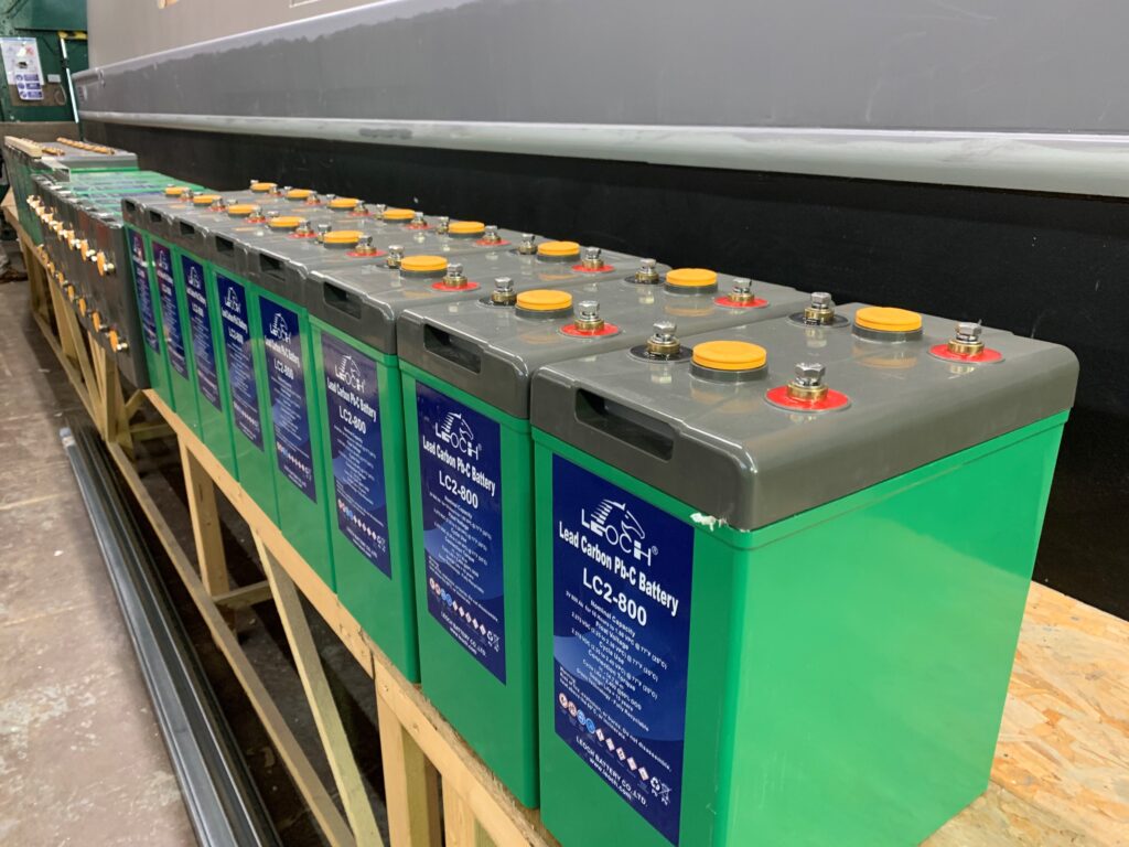
We average around 9kWh of power consumption every day when moored, which includes cooking an evening meal, but not water heating which typically consumes around 3kWh for enough hot water for two people to shower. In addition our propulsion typically consumes around 1.5kW per hour of cruising.
The size of your battery bank will dictate how often you have to run the generator, so it is an important decision to make. Our 48v 800Ah battery bank on “Old Nick” provides 38.4kWh of power of which 23kWh (60% is useable). With no solar at all (never happens) we could cruise for 1.5 days (6hrs per day), without running the generator.
For most of this month we have been averaging 7-10kWh of solar, so that significantly reduces the amount of time the generator is on and with the odd visit to a marina every couple of weeks, this reduces even further.
We feel 800Ah of Lead Carbon or 600Ah of LiFePo4 is about the minimum battery bank required on a boat fully dependant on electricity i.e. no gas or solid fuel. However, it goes without saying, that space and budget permitting, the larger the battery bank the better.
The Generator
The “dirty” component of the serial hybrid, is the diesel generator but this is also one of the most important parts if you wish to continuously cruise or spend weeks out of a marina.
They are expensive bits of kit, but surprisingly the cost to buy and install a Vetus 14kW model is only 20% more than the 6kW model that we have on “Old Nick” and yet you are getting over twice the power output and only marginally higher fuel consumption.
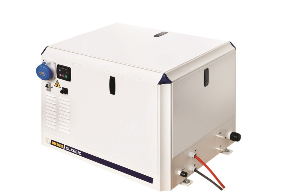
Much as we try not to, we sometimes have to run the generator to charge our batteries, so it would be far better to run a larger generator for less time (particularly when moored near other boats), have the extra generator power to help preserve battery life on long river passages or charge the batteries in less time, while cruising on a canal.
A larger generator, is definitely something we would seriously consider, if we were starting again.
The other decision to make with the generator is whether to have a dry exhaust or wet exhaust system. A dry exhaust is technically a better solution, where you have a skin tank of coolant that cools the engine/exhaust. If you decide to have one of these, make sure that the skin tank design is suitably large and capable of efficiently transferring the large amount of generated heat. We have heard reports of, some dry exhaust installations, overheating when the boat is stationary in summer months.
A wet exhaust, as we have on “Old Nick”, uses canal water to cool the engine and its exhaust gasses. Then it uses a separator to discharge the cooled gas and water through different outlets. This is quite a common and well proven system on sea-going vessels, but the muddy canal water can cause filter blackages and shorten the life if the water pump impeller. We have a regular routine of cleaning our raw water inlet, basket filter (every 2 weeks) and replace the impeller every year, just to be on the safe side.
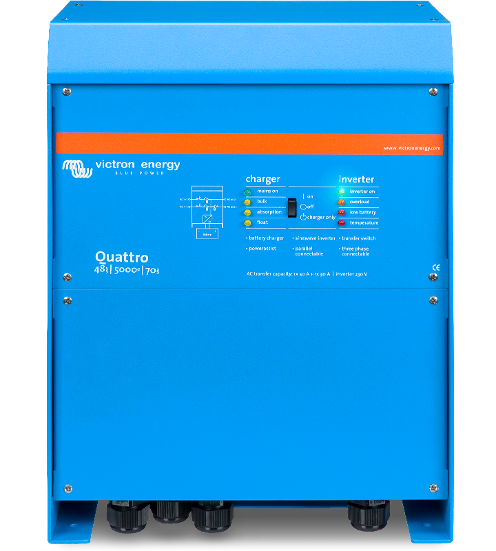
Battery Charger/Inverter
At the heart of the serial hybrid system is the battery charger/inverter, which in the case of “Old Nick” is a Victron Quattro 48v/8000VA – a 110A battery charger and a 8000VA (6500W) inverter. A Quattro has two AC inputs – one for the generator and one for the shore connection.
With our 6kW generator, we typically set the Quattro to limit AC output to 23A, just over 5KW so that the generator is not always operating at its maximum output. When on shore power the Quattro is set to limit AC output to 13A, to minimise the chances of tripping the marina’s electricity bollard.
We have never needed more onboard AC power than the Quattro can provide, regularly running the kettle, hob and oven at the same time. but if we had a larger generator, it would make sense to fit the larger 10000VA version so that the battery charger is better matched to the generator.
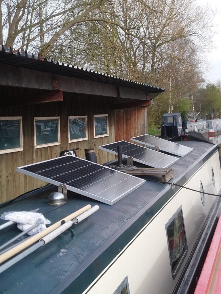
Solar Panels
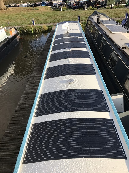
One area where it makes sense to go as large as possible, is solar, after all once the panels are bought, it is all free energy.
The biggest decision is whether to go for rigid panels or semi-rigid panels. There is no doubt that the rigid panels are more efficient, but only if you remember to tilt them towards the sun, which when regularly moving is an extra chore. By comparison, the semi-rigid panels will always provide a good level of solar yield and have the added benefit of not snagging ropes and being walkable on.
Our 12 x 160W panels have generated over 6 Mega Watts in the last four and half years and despite being relatively old now, are still regularly keeping “Old Nick” in the daily top 5 of Ortomarine boat’s solar yield, despite some of the latest boats having 14 x 200W panels.
240v AC Shore Connection
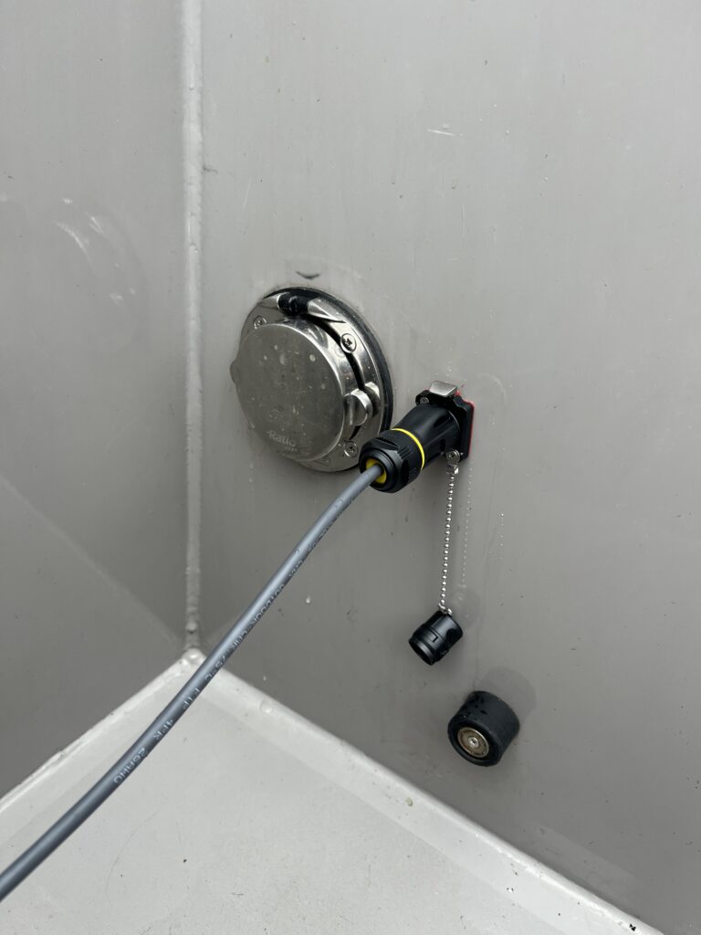
One final design decision to make, is what size of AC Shore connector and cable to fit. When we were specifying “Old Nick” we decided to go for the larger 32A connector, in the hope that more marinas would start to fit them. Adoption has been pretty slow and for most marinas that we visit, we have to use our short 32A to 16A adaptor and accept that we will need a full overnight charge (approx. 10-12 hours).
Last year when we did the Grand Union, we did get to plug in to a few 32A charging points and managed a full charge in 4-6 hours, which was great and I would probably recommend fitting a 32A connector and cable if you have the budget. Aqua Vista fitted a new Rolec fast charge bollard at Electrika last year and I hope that more marinas will follow their lead.
Data Monitoring
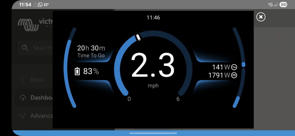
We have been spoilt with our “Ortomate” control and monitoring system, that Ortomarine boats have as standard. Every aspect of the serial hybrid’s performance can be monitored and displayed and it is amazing how it has become part of our daily routine.
Three key data measurements should be mandatory on all electric narrowboats – Motor RPM, GPS speed and Motor Current or Power. With these three key pieces of information you can optimise your cruising behaviour for minimum energy consumption, quickly detect issues like weed on the prop and avoid excessive current draw because you cannot hear you are going too fast!
For those not lucky enough to have an “Ortomate”, Victron are now making it a lot easier to monitor most of this critical data on their Cerbo GX with the latest V3.60 firmware. Connect a GPS sensor (via USB or NMEA2000), feed in the engine data via NMEA2000 and the Cerbo GX will create a rather good new “Boat” Page.
In Summary
We along with many other happy owners, have proved that the technology needed to design a reliable and efficient serial hybrid, is definitely available now. That said, it is still possible to make mistakes. Our hope is that if people like us share our positive experiences, shows like Electrika help educate potential owners and the industry follows the lead taken by boat builders already creating successful designs, more and more boat owners will be able to safely enjoy “going electric” and the benefits this technology brings.
You no longer need NMEA2000 to feed motor data into the Victron “Boat” page, there’s now an easy-to-install driver to allow direct CANbus connection from the motor controller to the Cerbo GX.
Apart from that I agree with pretty much everything you’ve said — I too have a 16″ x 12″ 4-blade prop but with a high-torque motor which can push out up to 15kW. Note that the new Vetus 22kW motor isn’t high torque because that’s at 1500rpm, much too high for canal use.
One point to note is that the Victron Multiplus/Quattro can’t sustain the full data sheet charging current for very long, this drops as it heats up — I have a Quattro 48/10000 and 35kWh LFP battery (and 9kW generator), and have never seen the full 140A charging current, it usually drops to 120A and then 110A after an hour or so, and eventually to 100A if you run for several hours.
Hi Ian,
Interesting about the Quattro. Our Lead Carbons probably don’t push it as much as your LiFePo4s but I have looked at the charging current on occasion and expected it to be higher. I can forgive it a lot though as it is going 24/7 and never misses a beat – an amazing piece of kit.
The Sevcon support will be useful for those that have that controller, but for others (myself included) NMEA2000 will still be relied upon for getting the data in there.
Best regards
PAUL
Hi Paul
The driver should also support Curtis controllers, if that’s what you’ve got. Of course if you already have NMEA2000 you already have a working solution… 😉
Cheers
Ian
Hi Ian,
The Vetus motors have their own Vetus designed controller, which uses V-CAN the Vetus flavour of CAN. They offer a small CANverter unit that converts V-CAN to NMEA2000, both for the motor and bow/stern thrusters.
Best regards
PAUL
Nice! It was great meeting you at Electrika this year.
I also have lead carbons, as Lithium was far too expensive for me.
And yes electric motor technology offers many more options now compared to 5 years ago.
Just wondering what you think of using a DC Genset rather than an AC one.
Hi Jamie,
When you consider that all gensets have to generate AC voltage (even alternators) and then rectify and regulate the DC output, I cannot see the benefit in a DC generator as I am sure the efficiency will be less, than an AC generator.
Couple this to the fact that for efficient battery charging, the DC output must be an intelligent multi-stage battery charger, matched to the battery chemistry of your battery bank and not just a “dumb” alternator type output.
I prefer to have an AC output genset feeding in to the second AC input of a Victron Quattro and then utilise the proven and intelligent multi-stage battery charger of the Quattro.
Finally, the cabling of the AC generator is simple – just a suitable 32A mains cable with little concern about voltage drop – while for a DC generator wiring is going to have to be pretty much the same gauge as the Battery cable and will restrict where you can locate the generator.
This is just my opinion and I have not really studied the latest DC generator models – what model did you have in mind?
Best regards
PAUL
Hi Paul,
Your point about the wiring is on point, but if your genset is next to the motor, as yours is, then it’s not too much of a worry.
As regards efficiency, the DC one may well be better, as you don’t have the additional loss of the charger to go through as well. There is also possibly a better reliability because there is one less piece of electronics between the genset and the motor, and at a pinch you could run just the two to get you to a place of repair if it all went horribly wrong.
Furthermore, the genset’s speed can adjust to the charging current required helping to maintain the genset’s diesel motor’s efficiency, an option not available to the AC genset.
I hear what you are saying regarding Battery charging, however really one should only be using the genset for bulk charging, and not the absorption phase, another reason to pivot to LiFePO4!
TBH it’s swings and roundabouts, like any engineering problem.
I’ve gone the DC route using a Fischer Panda AGT 6000 48v Generator in PVMV-N
Best regards,
Jamie
Excellent post Paul. Re the use of the Quattro for charging vs direct DC – surely it makes no difference if the Quattro is set to use the BMS to regulate charging? What am I missing?
Hi Nigel,
Sorry for the slow response.
The issue is whether it is better to have….
1) An AC charging output from the generator going to the Quattro and then letting the Quattro take care of charging, either through the traditional multi-stage battery charging circuit or by CAN communication direct to the LFP batteries BMS.
OR
2) A DC charging output from the generator going directly to the LFP battery bank.
I have not studied the efficiencies of the two methods, and there maybe some benefits to the DC genset route, but I would be interested to know how the Fischer Panda generator handles LFP batteries. When they reach full charge and the BMS disconnects, how does the FP genset cope with the sudden “no load” situation, which can cause problems for alternators, and does the FP genset communicate directly with the BMS(s) as the Quattro does?
Best regards
PAUL
It’s doubtful that there’s much difference in efficiency — in one case (AC generator) the alternator directly generates 230V AC 50Hz, the Quattro then converts this to 48V DC using switching MOSFETS. In the other case (DC generator) there’s still an alternator inside the generator, and a similar switching stage to the one in the Quattro to convery the output to 48V DC.
If the BMS disconnects then that’s bad news in all cases, the right solution is for the BMS to control the charging sources and turn the current down and then off. This is easy with an AC generator/Quattro, not no easy with a DC generator unless it’s also integrated into the Victron VE.CAN system.
Interesting point with regards to BMS disconnect.
I was thinking about Lead Carbon, which is a different issue.
I do know that for those the DC generator stops at the end of the bulk charge cycle. So at about 85% charged. It does not run for the absorption cycle, as that would be inefficient.
Obviously if it did the same for LFP batteries there wouldn’t be an issue.
However, measuring that point would be difficult I think!
An excellent article Paul. Enough technical info to be useful without going over the heads of most laymen or women.
Just the sort of thing we need to balance out some of the more sensationalist negative press that electric boats have been getting of late. Well done.
Very interesting article.
I am an electronic engineer and have been 100% solar for well over 10 years now in my non floating and hopefully very stationary house. I am also using lead carbon batteries. At 750 Ahr they weigh around 940kg and take up about 1 cubic metre of space. Not a problem for a stationary installation but space (the final frontier) is quite likely at a premium in a narrow boat. Is weight a problem?
Solar panels are quite good now and offer excellent longevity and better temp. co. figures. I would also imagine it can be a bit of a pain having to adjust your panels to point sunwards whenever you go round a bend. This calls for an auto directional (plus tilt?) device.
A fantastic project which can only add to the relaxing enjoyment of silently motoring around the UK canal system.
Hi Jamie Angus.
Ref. your comment:
“However, measuring that point would be difficult I think!”
LFP chemistry batteries are charged in a similar way to lead acid of all types.
CC/CV which is shorthand for constant current /constant voltage.
The differences are that LFP does not require trickle or float charging the reason being that LFP batteries can hold their charge for years with little loss but not so the lead acid chemistry.
LFP CC charge cycle the current is pumped into the cells until a preset voltage is reached. At that point the charge controller will change to constant voltage charging during which the voltage applied remains constant (no surprises there) and the current flowing into the battery will gradually diminish. At a predetermined point the current is so low that the battery is considered to be fully charged and the BMS disconnects.
What does the generator think of all this?
If it is a half decent generator, it’s output voltage will automatically stabilize regardless of the low current demand. When the BMS/charge controller disconnects the battery from the charger the generator should also receive a stop signal.
Hi Terry,
I’m an electronic engineer too! I understood that the voltage vs charge curve was flatter. I now notice that there is a definite knk at around 90% that one could use to stop charging.! So yes that should work just fine.
Going by measurements on my batteries, there isn’t enough of a kink anywhere below about 95% SoC to stop charging; all BMS just use hitting a voltage limit (and good ones also use cell imbalance) to decide when 100% SoC is reached, then allow voltage to drop back to a lower float voltage. On mine float is 54V (about 99% SoC), 100% SoC is 57.3V, voltage stays almost flat up to 95% SoC and then rises above this.
Hi Ian Dedc,
I agree with everything you said especially the mention of the cell balancing. That plays a significant roll in reaching full charge of the entire pack.
When all individual cells in the pack reach their maximum voltage (typically around 3.4V to 3.6V for LFP cells) and are at the same level, the BMS recognizes the entire battery pack as fully charged. The BMS will then stop the charging process by disconnecting the charger, signaling the completion of the charge cycle.
This is more or less what I had intended to say except that I used the diminishing current of the CV cycle to say it. When all cells are fully charged there should be no further current flow and this is what the BMS has been waiting for to end its charging activity.
It is this that makes LFP’s more suitable than lead acids for solar systems however my lead carbons were loads cheaper than LFPs so this downside was acceptable.
Next will be solid states for me………..
In my case (REC-BMS controlling Cerbo/Quattro) the charging is all controlled using CVL (Charge Voltage Limit) and/or CCL (Charge Current Limit), there’s no “turning off” of charge sources as such. Once 100% SoC is reached (57.3V battery voltage, 10mV cell imbalance — CCL is used to hold in this state) the CVL drops back to 54V over a few hours (due to load current draw) and stays there until the next cell balancing cycle is commanded (every couple of weeks). In response to this all the charging sources (MPPT, shoreline, generator) drop current while balancing and then stop charging until the voltage drops back to 54V, given the CVL and CCL broadcast by the BMS and enforced by the Cerbo/Quattro — they don’t have any “intelligence” of their own apart from obeying these limits, the BMS is the master and everything else are slaves.
See here for an example at the end of my last trip (charging from solar) — when voltage hits the CVL the BMS drops the CCL to just enough to drive the loads, cell balancing then took about 4hrs (the boat had been out cruising for a week or so, and moored without a balancing charge for several weeks before that — and 16S 700Ah cells take a long time to balance…). When balanced, SoC resets to 100%, then voltage drops back until the sun comes out the following day to charge back up to 54V/99% SoC.
https://drive.google.com/file/d/102IkX77MPZUAbq7NDbJHjHYLBOB_A7gA/view?usp=sharing
Hi there,
I left a long and winding email last night and this morning i deleted my junk box and then i panicked that i may have deleted your response. Then i realized that I’m panicking for nothing because my rambling email required much thought for a response. either way, if you have responded to my email before this email here, please resend in case i accidently deleted it.
Hi. Don’t seem to have anything from you?
I may have emailed you directly. My partner and I (currently living in Brooklyn NY) are planning to retire September 2027 to cruise the inland waterways of Europe (France, Belgium and the Netherlands) on a 60 times 14 foot widebeam and we really want it to be electric propulsion. However electric cruising has not taken off in Europe as in the UK and the organization I’m a member of , the Dutch Barge Association (DBA) has many nice and experienced cruisers that doesn’t think it’s possible given that the larger canals and many more rivers than the UK. Their fear is that the electric motor will not provide enough power to be on the rivers, especially. I’m not at all tech savvy (I work in finance and my partner is an educator professional and I understood about 60% of the technical stuff in your article). I know you have a narrowboat in the UK and have not cruised in Europe but I still wanted your opinion, if you have any, on whether the technology that you saw at Electrika 2025 and your pretty in-depth knowledge or other existing technology, of this is a pipe dream of ours.
Hi Ardis,
A serial hybrid 60ft x 14ft widebeam could be designed that would give good performance on the European inland waterways, but it is a major challenge and I honestly don’t think the availability of suitable system components is there yet.
To match the torque and power of a similar diesel powered craft, you will need to over spec the design to cope with long periods of river usage. I would estimate that you would need to tripple or even quadruple the setup we have on our 58.5ft narrowboat. This equates to 100KW/h of battery storage a 30-40KW engine, 30KW battery charger and 6KW of solar.
The electrical system, at least for propulsion would really need to be 72v or 96v otherwise your cabling will be mega large and the whole installation would be a step up in terms of leisure marine vessels – probably requiring design and installation by a super yacht or commmericial shipyard that has the suitable experience of designing large EP systems.
Much as I would love to see such a design take shape, I think the cost and risk is prohibitive.
Sorry I could not give a more positive response but I had to be honest and realistic.
Best regards
PAUL
Thanks for your honesty Paul. I’m not totally surprised as I have been hearing from other folks that didn’t they didn’t think it was possible. None of them had the technical background/knowledge you have. Just one more question, do you think a parallel hybrid system could work?