
So – we have chosen our batteries from Leoch, selected the electric engine and generator from Vetus and decided to go for 10 solar panels from Photonic Universe. However, there is still one very important “piece of the puzzle” to be solved and that is the energy management system.
If we refer back to the Electric Serial Hybrid drawing, you will see a component simply referred to as “Battery Charger”. This made the diagram simple, but hugely under valued this key component in the system.
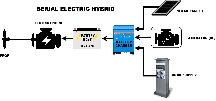
We deliberated on the best name for this component, or what in reality is a series of components, and finally christened it; The Energy Management System (EMS). This post will endeavour to describe what the EMS is and which manufacturer’s components we chose.
Let us start by expanding the Electric Serial Hybrid diagram, focusing on the “Battery Charger” section and at the same time detailing the components we have already decided upon.
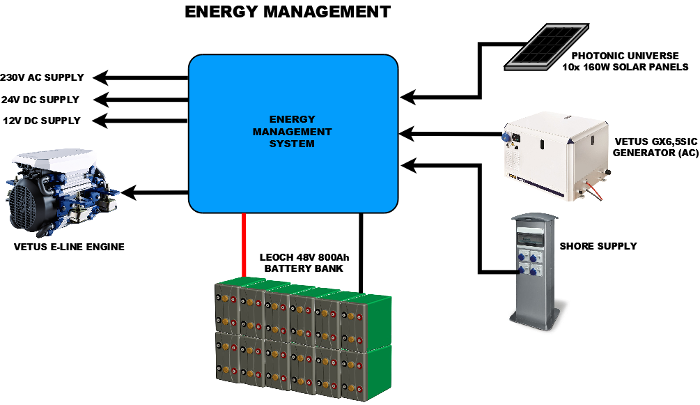
As you can see, energy is received from any of the three sources on the right side of the diagram and the first thing the EMS has to do is decide which is the best energy source to charge the batteries.
This involves monitoring the sources to see if we are plugged in to the shore supply, checking if the generator is running and also managing the solar panels. When there are AC “mains” power sources available the EMS will use its own battery charger to charge the battery and if no AC sources are available, then the MPPT controller will take over the battery charging, sunlight permitting.
In addition, the EMS has to manage the AC power on the boat, switching either of the two AC sources through to the boat’s AC sockets or if neither are available, using its own inverter to generate AC power from the DC power of the batteries.
Finally the EMS must supply all of the DC “battery” supplies required, which on “Old Nick” will be a 48v for the engine and inverter, 24v for most utilities and 12v for any equipment that is 12v only.
So the EMS for “Old Nick” will look like this…
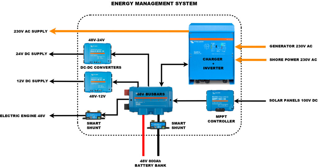
I am sure you cannot miss the amount of “blue” in the diagram and many of you will have guessed that the equipment for our EMS will be coming from Victron Energy, the very popular Dutch manufacturer of energy solutions for mobile, remote and “off grid” installations. Thousands of UK canal boats have one or more Victron products and they are generally regarded as the leading brand in this market sector.
What is missing from the diagram above are the data connections between the Victron units. One of the strengths of the Victron products, is their networking and interfacing capabilities. The Quattro Charger/Inverter, MPPT controller and two smart shunts, all talk to each and provide a complete picture of what energy is being used/generated and where it is going to/coming from. They even do a smart bus bar, which would have been nice to have, but I had to keep one eye on the budget!
One very important device that is not shown in the EMS diagram, and in fact is not needed for the EMS to operate, is the latest Cerbo GX box, that is the “icing on the cake”. This compact, unassuming box connects to all of the devices and allows you to monitor, control and configure the EMS. This is all done through a simple wireless web interface, that you can view on your phone or tablet’s web browser – no special app required.
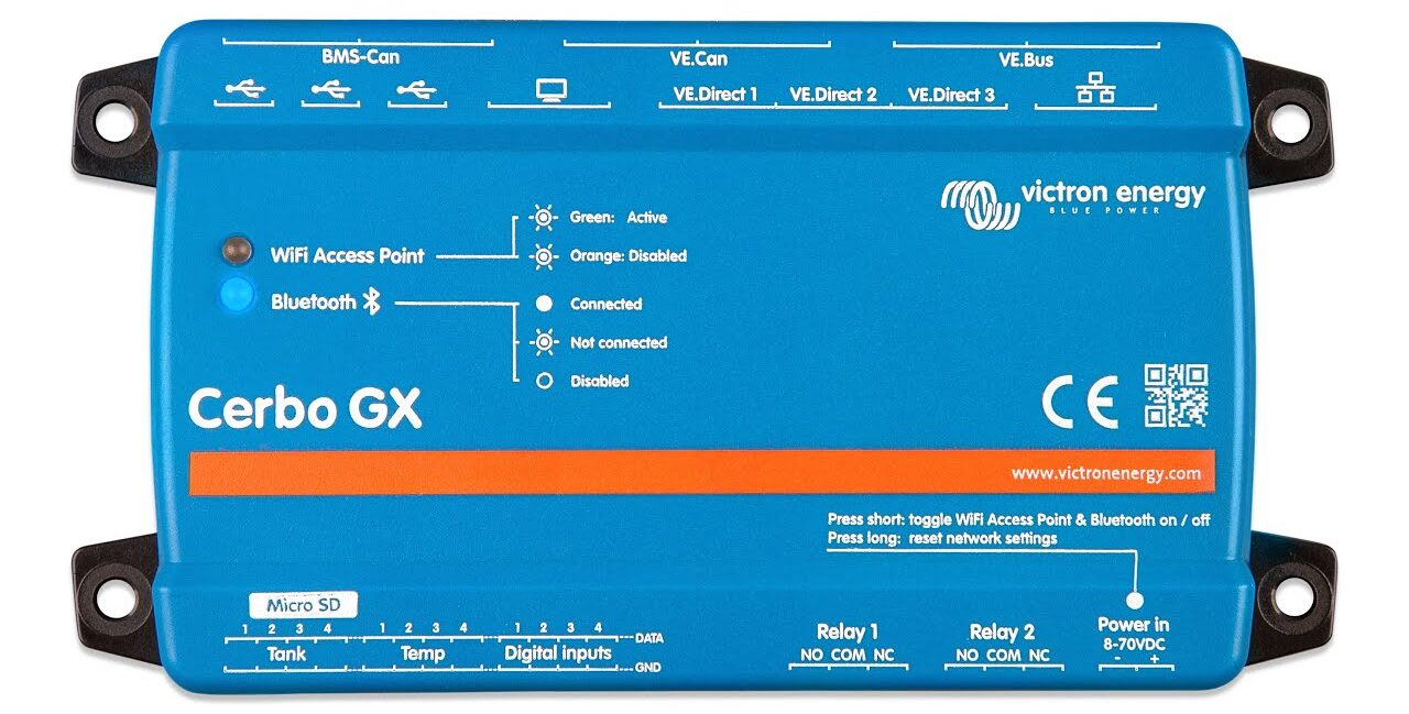
Victron Cerbo GX 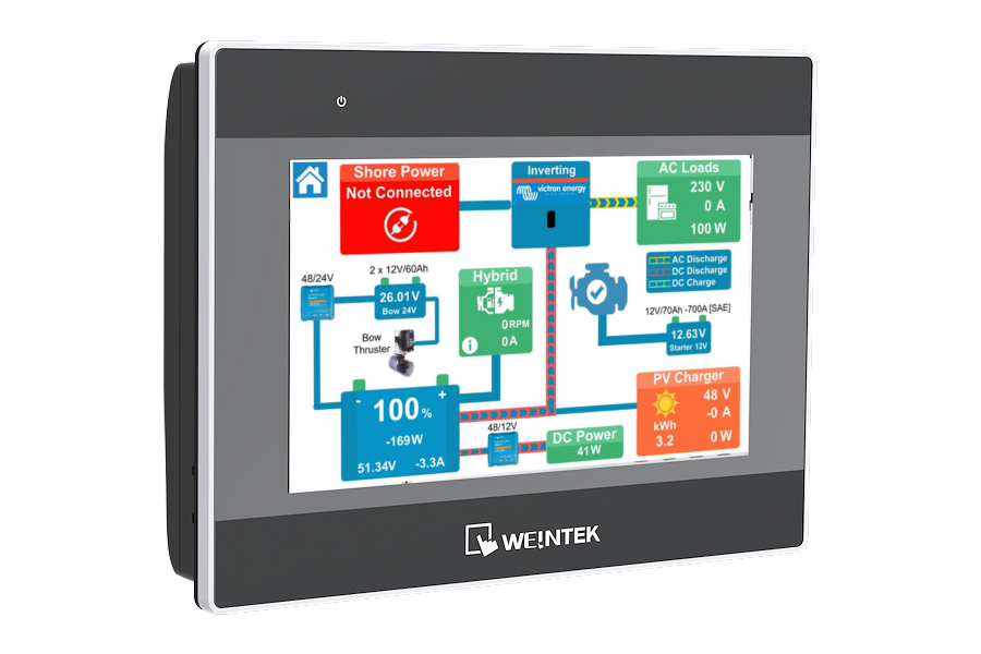
Ortomarine Touch Screen Controller
What the Cerbo GX will also allow us to do, in conjunction with Ortomarine’s, powerful and intelligent Touch Screen Controller, is allow the EMS, plus other important equipment and services to be centrally displayed, monitored and controlled on a dedicated colour touch screen. In addition, all of the data can be automatically uploaded to the cloud for remote monitoring and analysis.
Aside from our own personal interest, we hope that this cloud data (when published) will give Vetus feedback on the power usage and performance of their new E-Line engine, whilst also providing “real-life” data for anyone wishing to follow in our footsteps and make the jump to electric propulsion.
Another mind-bending, for me, trip into the baffling world of battery management! I am so pleased that you will have a gizmo that shows you the state of your batteries at the touch of a button! As I recall it required a certain amount of know-how on Sam!! X x
Hi Paul,
Thanks for putting the effort into describing your system.
One thing that caught my eye from your diagram is the 2nd SmartShunt between the engine 48V and the DC Bus.
Unfortunately for now at least, the SmartShunt is only suitable for use between the Battery and the DC bus, to count Amps, Amp hours and keep track of system state of charge.
I hope one day it can be used as a seperate DC current monitor for things like external loads and charge sources, but for now in this situation I do not think the additional SmartShunt will do what you are hoping (which I presume is to isolate the energy/power consumption of the electric motor from the other DC loads).
Hi Guy,
Thanks for this warning. I checked with Rob at Ortomarine and he agreed that generally it is not recommended to have two Smart Shunts, but he has been working with your Level 3 support team and is running some beta release Cerbo firmware that fixes some of the issues, related to having two Smart Shunts.
He has managed to get all of the Cerbo display pages working correctly and is also reporting all of the right data to the VRM Portal. He is only using the Engine Current and Voltage values not SOC and other readings, but so far it all seems to be working well.
Hopefully by the time we get to “Old Nick” the firmware might be officially released and everything will just work!
All the best
PAUL
Did the SmartShunt in the motor lines work in the end? We have a similar basic arrangement on Nautilus-Enterprise and the motor consumption is included in the DC-consumption guesstimate. I would assume that a mature firmware would understand the current into/from the battery, the MPPT current, Quattro current, and the motor current, and render it all correctly to the GX. Sadly the motor data frames on the VE.CAN does not send motor current into the system.
Hi Peter,
In the end our final installation on Old Nick, did not use a second Victron Smart Shunt, as we found that we could pick up the engine current from the Vetus V-CAN data – converted to NMEA 2000 and displayed by Ortomarine’s Ortomate system.
However, for people that cannot go the CAN route to get the engine current data, then a second Smart Shunt is the way to measure engine current. Install the shunt in the negative cable to the motor, take the supply voltage for the Smart shunt from the 48v feed to the motor and you will be able to read and display Engine Voltage and Current on the Cerbo GX. You can even select what the Smart Shunt is connected to, see this link to the manual….
https://www.victronenergy.com/media/pg/SmartShunt/en/all-features-and-settings.html#UUID-a8b42cd2-2e6d-c938-d60c-4ae2beea0e0a
Hope this is useful.
Best regards
PAUL
I’m enjoying your blogs.
I’m wondering whether you considered putting in some 5V DC supply circuits into the boat?
You likely have a number of 5V consumer electronics that are charged via USB, and it seems wasteful to invert to 230V just to convert down to 5V again to charge mobiles or speakers or so on. If you were to install USB-A ports on the sides of the boat linked to a dedicated 5V line you’d be able to charge them directly off the batteries, with a maximum 2.1A draw per socket, which allows for a rudimentary amount of power management (no more ports than the batteries can support) and possibly switched sockets. If you want to be cutting edge, USB-C delivers up to 100W power (20A draw), which can power some very hefty laptops, but allows for intelligent negotiation, so you should be able to limit the power draw based on battery/engine status, if you can find a compatible power supply.
Hi Giles,
Glad you are enjoying the blog and thanks for the comments about 5V USB supply. We are definitely having USB sockets in every cabin but I think Ortomarine run these from the 12V circuit or perhaps even the 230V mains circuit (I need to check).
It does seem odd to take the 48V DC batteries, convert them up to 230v AC, only to then convert them back to 5v DC, but there is “method in this madness”. On a 58ft Narrowboat, there is limited space for running cables from Stern to Bow and because of the length of cable run involved, you need very thick (low resistance) cables to carry the current, without causing “voltage drop“.
The lower the supply voltage the more effect the voltage drop has i.e. 0.5v drop in a 48v circuit is just a 1% loss, while in a 5v circuit it would be 10% and probably enough to cause problems with some USB devices.
For this reason it is actually good practice to have a limited number of supplies, just the highest voltage ones, running the length of the boat and then convert to lower voltages close to where the power will be used. So for instance, the bow thruster at the front of the boat, will have its own set of 24v batteries, which will be charged via a 230v AC battery charger, so that we only have to run the 230v AC mains down to the bow. Hope my explanation makes sense and I am not “teaching granny to suck eggs”!
On the USB-C question, I think I will keep an eye on this and perhaps install a couple of USB-C charging points later on – at the moment, I do not actually have any devices that have a USB-C input, but I am sure that will change soon.
Cheers
PAUL
Thank you Paul,
I was unaware that the voltage drop on a 5V circuit is that high over the length of the boat, and yes, it makes sense to lower it at the socket level in that case. I was working on the assumption that it was negligible over that distance.
Do consider going straight to USB-C – the power draw implications are quite different if done properly, and you can buy USB-C cables that will plug into any modern phone, tablet, or microUSB socket for a very modest price. Going from USB-A to USB-C in the future will imply some rewiring, or plugging in a power adapter into your 230V.
Cheers,
Giles