Computer networking is nothing new in many areas of our lives, but on narrowboats it is still fairly unusual and so it may come as a surprise that “Old Nick” will have not one, but four separate networks onboard, all tied together by Ortomarine’s Touch Screen Controller.
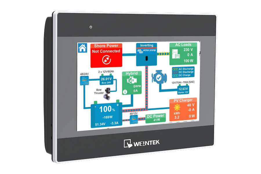
In this post, we will not only look at the important functions that each of the four networks perform, but also how Ortomarine have combined them in to one big network and the benefits this provides.
As “Old Nick” is an electric narrowboat, let’s start with the all new Vetus E-Line electric engine. Traditional diesel engines had a mechanical, cable-based “Morse” controller, which set the speed and direction of the engine. Many new engines though; both combustion and electric, now use an electronic “CAN” network to link the engine, display (gauges) and controller together.
CAN stands for “Controller Area Network” and is a relatively simple and low cost network, developed by Bosch for the automotive industry in the mid-eighties. The “CAN Bus” has become ubiquitous in modern cars, where you will typically find multiple networks and over 70 ECUs (Electronic Control Units) linking everything from the airbags to the wind screen wipers.
Adoption of the CAN technology outside of the automotive world has also been very successful, with a number of different “flavours” evolving to meet the specific requirements of other industries. In the marine world you will predominantly find NMEA 2000, the CAN protocol developed for boats, and also J1939 which was developed for the truck and heavy-duty vehicle industry.
In addition to these standard CAN protocols, many engine manufacturers have developed their own proprietary protocol, to give them added security and functionality. Vetus are no exception and their V-CAN technology is at the heart of the E-Line engine and also their BowPro Thruster range, one of which will be fitted to “Old Nick”.
If we look at how the various Vetus parts connect, we can see that the network cabling “daisy chains” the components together. All CAN networks must be “terminated” which basically means that a special 120 Ohm resistor is fitted at each end of the network (to stop the data leaking out 😉). Also it is quite common in some CAN networks to power the CAN interfaces through the network cabling. In the V-CAN network the 12v network supply is turned off/on via a neat key switch, to disable the engine.
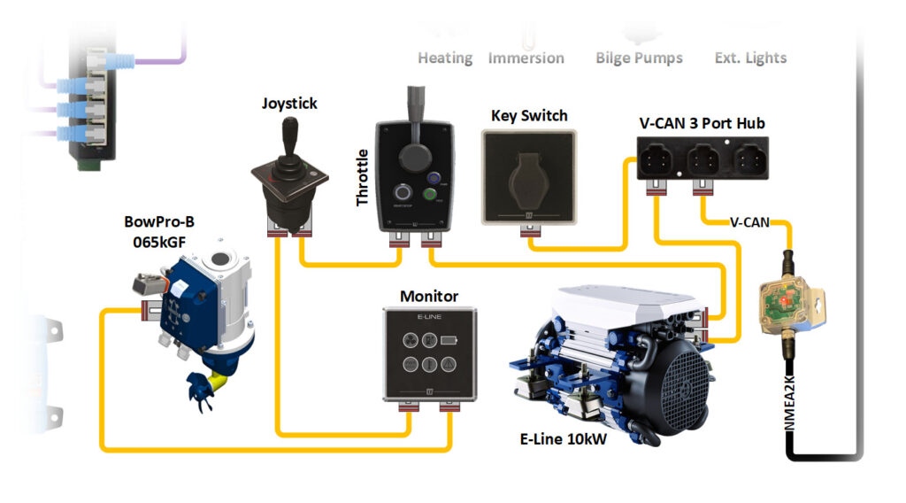
The V-CAN network is the longest network on the boat, as the engine is at the stern and the thruster at the bow, so a long 25m network cable is required. Microprocessors in the engine throttle and the thruster joy stick send commands down the bus to the respective device, while the engine monitor is listening out for messages on the status of the engine.
One additional, but very important device on this network is the V-CAN to NMEA 2000 converter which, as the name suggests, converts the proprietary V-CAN messages to standard NMEA 2000 messages. My aim is to use my knowledge of NMEA 2000 to display the data on Ortomarine’s touch screen controller and perhaps the odd iPad, iPhone or other wireless device – more on that in a future post.
After the propulsion network, comes the power management network, courtesy of Victron, whose blue boxes dominate the diagram below.
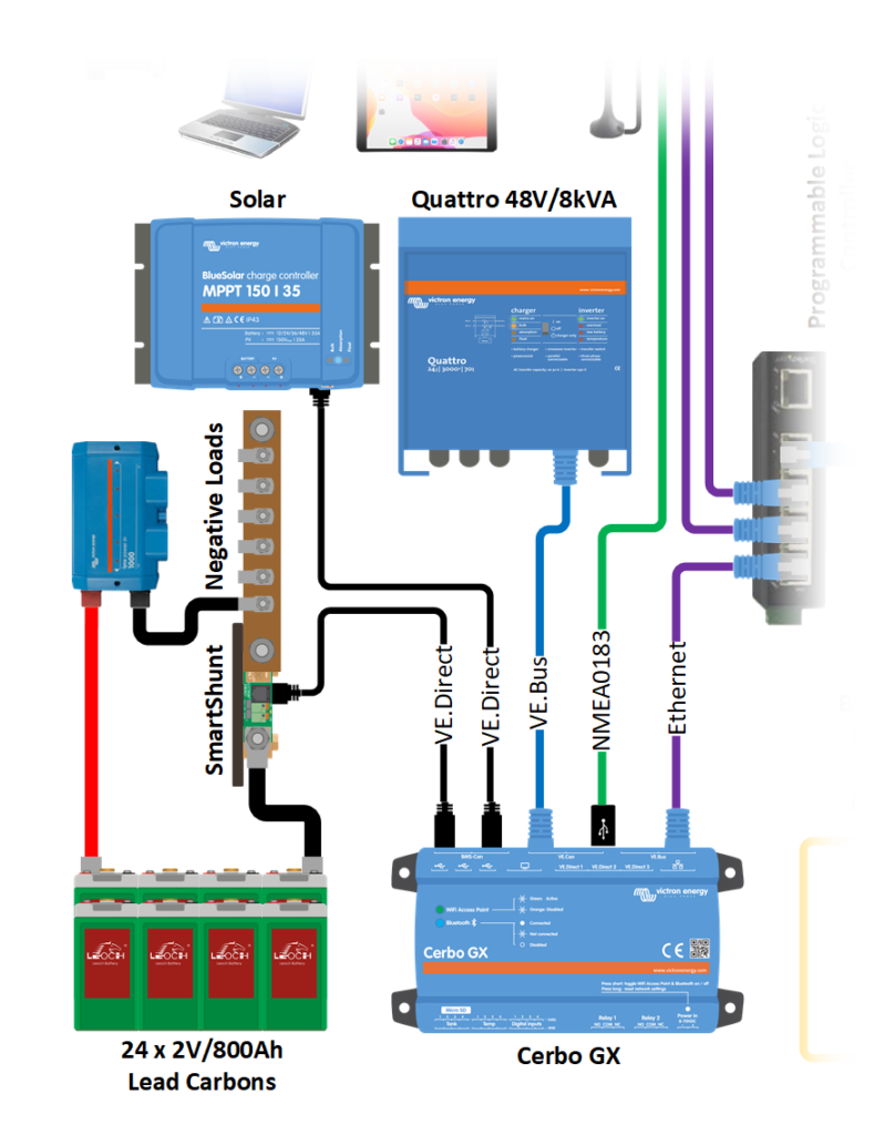
Victron have a great deal of experience in networking their products and support a number of different interfaces. We will be using their:
- VE.Direct interface, a simple 4 wire serial connection for directly connecting one device to another device.
- VE.Bus interface which is based on RS485 and allows multiple Victron devices to talk and listen to each other.
- Ethernet interface to connect to Internet/Cloud and communicate with the Ortomarine Touch Screen Controller.
- USB interface to get GPS position data from the 4G router
With Victron systems, you also have the possibility of using the VictronConnect App which gives you full access to the system via Wi-Fi or Bluetooth. This is a free app for Apple (iOS and OSX), Android and Windows devices, which I will write about once we are on the boat and using the system for real.
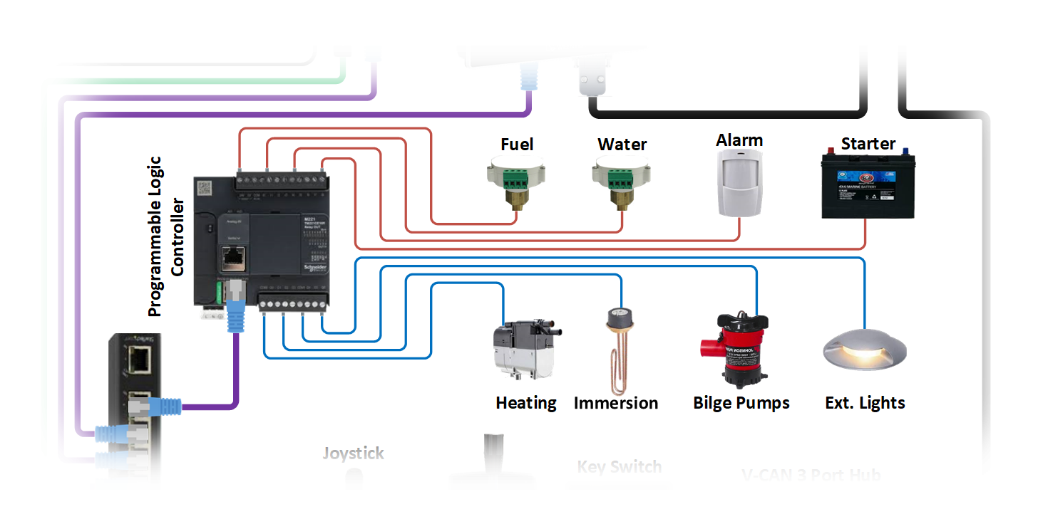
The next network to look at is the PLC network. PLC stands for “Programmable Logic Controller” and comes from the industrial and manufacturing process world. A PLC is basically a rugged and extremely reliable computer that can read sensors and control motors, relays and other devices.
On “Old Nick” we will be using the PLC to:
- Monitor the diesel and water tank levels
- Measure the state of charge of the generator starter battery
- Stop/Start the generator
- Control the central heating and immersion heater
- Turn on/off the external lighting
- Create a security alarm system
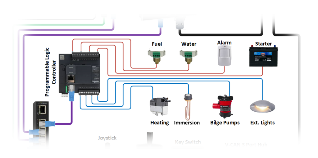
The PLC is programmed by Ortomarine and in conjunction with their Touch Screen Controller adds significant functionality and flexibility to each boat that they produce. Being able to add sensors, make intelligent decisions and automatically control devices, that on other boats are manually operated, is a very important and desirable benefit to boat owners. I am really looking forward to understanding more about this particular network and what we can do with it.
The fourth and final network is the one that you will probably be most familiar with – the Ethernet network. We are all used to being permanently connected now and this can be quite a challenge when you live in a “metal box” that moves around the canals. On “Old Nick” we will use a pair of external 4G antennas to pull in even the weakest mobile phone signals, which we hope will keep us connected in all but the most remote areas.
The boat’s wireless router will have a 4G Data SIM card fitted and will connect all of the boat’s devices that require internet access, to the same mobile broadband connection. For under £30 per month we will have unlimited data which will allow streaming to be our main method of watching TV. This has the added benefit of our terrestrial TV antenna becoming a temporary fitting and not taking precious roof space away from the solar panels – more on this in a future post.
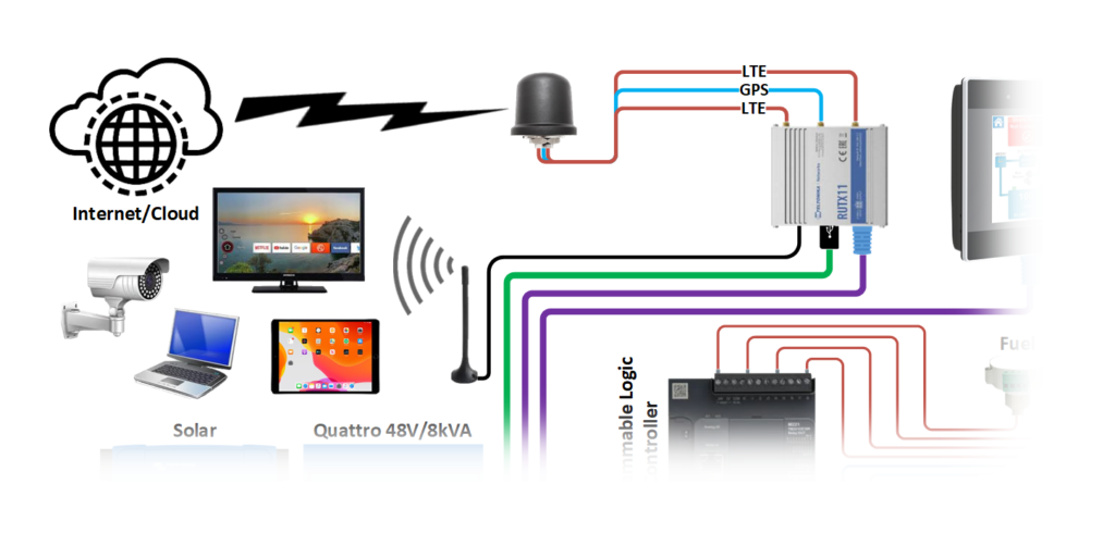
We have many devices onboard that need to be online, and also want to stream video so a fast wireless network is critical. Fortunately, the router we have selected, supports both legacy 2.4GHz and the faster 5GHz Wi-Fi networks.
In addition, the industrial router has its own GPS receiver, which is really useful for providing time and location to the data that we will be continuously logging from the boat’s systems.
Each of the four networks performs an important function on board, but it is when you join them all together that things get really interesting and you can start to automate and control the boat in new and innovative ways. We will cover these in more detail in a future post but for now, here is the complete network diagram for “Old Nick”.
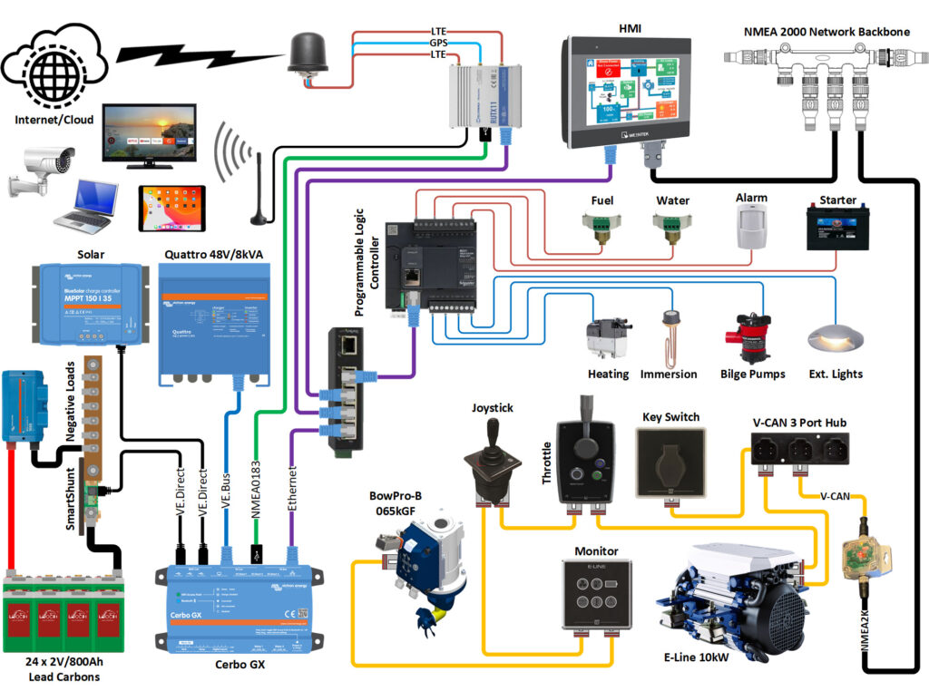
Courtesy of Rob Howdle at Ortomarine

Looks pretty impressive, the Teltonika routers are great – I’m using a RUT955 on my boat. My system is a bit more cheap and roll your own though – heavy on the raspberry pi and arduino stuff I had lying around before I started building the boat. Implementing Victron’s VenusOS on a Pi using the ve.direct and ve.bus USB adapters is amazingly quick and simple.
Hi Martin,
I will probably have a Raspberry Pi somewhere onboard, although I do have a spare older Venus GX box and I was thinking of running the VenusOS image that includes the Signal K server – have you seen this? Thought this was a bit too geeky for the main post but thank you for asking the question, perhaps I can do a separate post on this later on when I am on board and using everything for real.
Cheers PAUL
Haha, it probably is a bit geeky! I’ve seen the SignalK stuff but haven’t really had a chance to play with it yet. I believe the newer versions include NodeRED support as well. Mine gets even worse because of the slightly more complicated way I’ve got the 12v domestic system set up, not sure how I’m going to implement monitoring there yet!
Now I’m getting my geek head on with this. It’s not before time that the technology that we have around us at home and in our cars, was transferred over to the waterways. It’s goona be great to see everything up and running. Keep the posts coming, we love reading them.
Thanks. Good to know someone is reading and enjoying at least!!
I have crewed on 2 high end boats that were less than 3 months old recently. BOTH had PLCs. They both thought the holding tank was full and turned off the guest head. I did enjoy your post but beware of too much big brother.
Hi Jas,
Bet that was popular with the guests 😂. I must admit that compared to the systems on board modern super yachts, our PLC network will not be too complex, but things can still go wrong. Fortunately Rob at Ortomarine, our boat builder, has many years of experience in designing and programming PLCs in the Oil and Gas industry, so I have every confidence in our setup. Plus I have a direct hot line to him should any issues arise 😉
Hi, very interesting post and diagram. I have the same Teltonika router and a Victron GX. What actually is the green NMEA0183 connection between the Cerbo and the Teltonika? Is it a USB device? How is that working?
Hi Martin,
The green NMEA 0183 connection is GPS data from the built-in GPS receiver of the Teltonika, being sent out to the Cerbo GX. You need to make up a special USB<>Serial<>Serial<>USB cable but it works very well and gives a stable and reliable GPS source for the Victron VRM data.
Cheers
PAUL